Features:
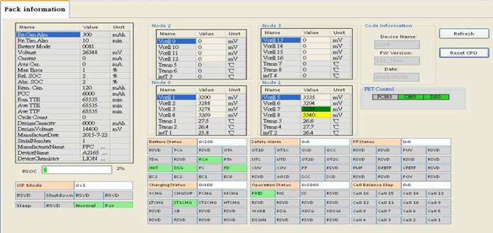
1. With Graphic User’s Interface over SMBus via USB tool kit to PC, to gain battery information, helpful for engineering services., monitoring battery SoC & SoH, such as Amperes, capacity; temperature, protection status and cell balance, event records etc.
2. Conducting back electromotive force (bemf) circuit design..
3. LED display module and tach signal switch, based on Coulomb Counter.(Option)
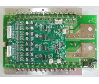
4. 2-tier system with Mosfet Switch board and monitor-control unit
5. Allowing test vehicle going on slopes of 30° (dgr), multiple surface as soft grass and mud.
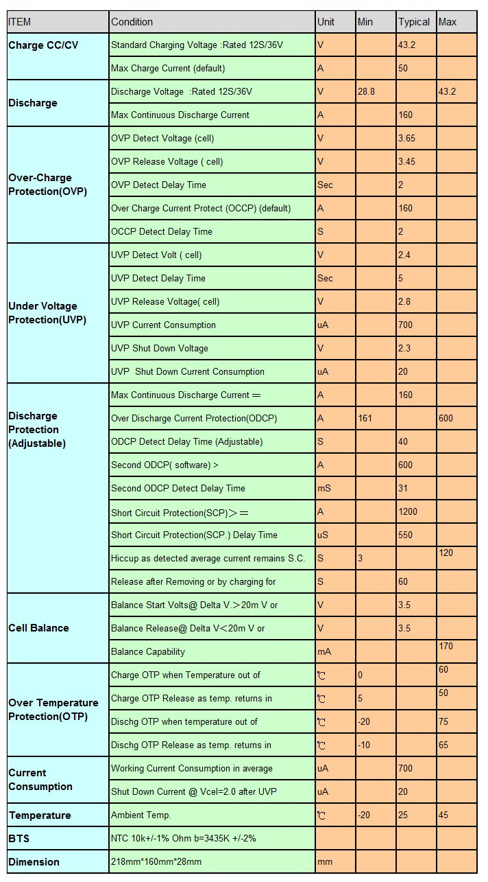
Specification:
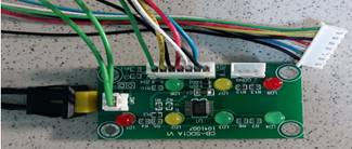
Fuel Guage LED display for Battery SoC (LED display on Pay for Option) 63mm*33mm*15mm
(1). LED board wiring diagram LED board with a multi-wire harness connecting to JB1 of BMS.
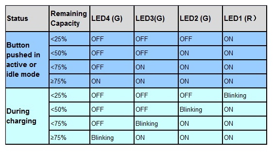
(2) State of Charge by LED display
(3) Smart battery management of SMBus via USB tool kit to PC(tool kit on Pay for Option).
Dimension:
Wiring Diagram:
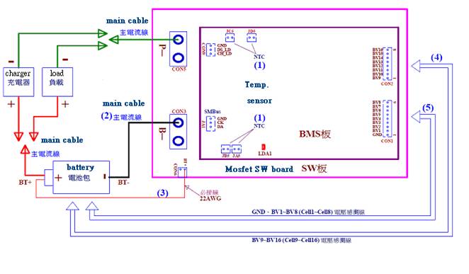
<1>. Steps to install battery pack with BMS. Please follow from (1) to (5)
(1) Plug temperature sensors, JA5, JB5, JC5, JD5 onto the BMS..
(2) "B─" at CON3 of the Mosfet switch board, connected to the "─” negative pole of battery pack.
(3) CON6 marked as "BT +" of the Mosfet switch board shall be connected to "+ (the positive pole)" of the battery pack. This cable is used to conduct possible Back-EMF energy.
(4) On battery pack, its "GND, BV1 ~ BV8 (Cell1 ~ Cell8) voltage sense wires" shall be connected to CON1 of the BMS board.
(5). On battery pack, its "BV9 ~ BV16 (Cell9 ~ Cell16) voltage sense wires" shall be connected to CON2 of the BMS board.
After these, the red LED (LDA1) of BMS board will turn luminous for about 6 seconds and then turns off,
This red LED indicator will blink at an interval of every 8 seconds, indicating BMS normally operating.
(6). Fuel Guage LED display for Battery SoC (LED display on option) [63mm*33mm TO BMS JB1].
<2>. Steps to uninstall:
(1). Remove link on the "P─" at the CON5 of the Mosfet switch board, which connects to the "─ “ negative pole of the charger" or "load".
(2). Disconnect or unplug each of its connectors according to the reverse order of the installation, from (5) – (4) – (3) – (2).