Features:
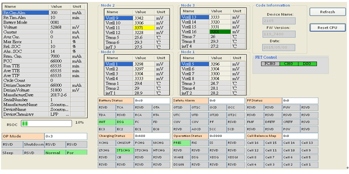
1.With SMBus comm. port via USB tool kit to PC, to gain battery information, helpful for engineering services.
2.Monitoring battery SoC & SoH, such as Amperes, capacity; temperature, protection status and cell balance, etc.
3.Conducting back electromotive force(bemf) circuit design..
4.Directed to design for a golf cart in need to run on grass ground and muddy ground and on a slope ground.
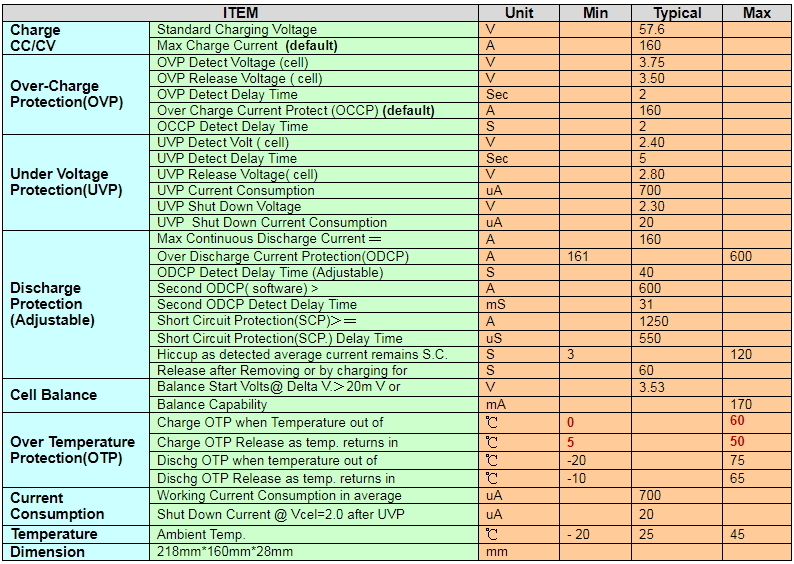
Key Specifications:
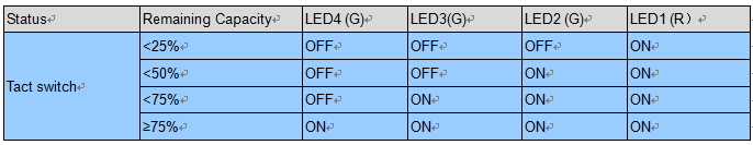
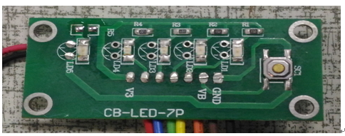
2.LED Display (Option)
(1).Battery SOC LED Module
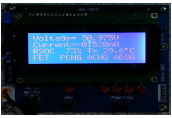
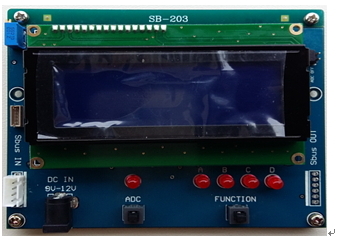
(2). Battery SOC LCD, with 4 display pages ,demands an external 12VDC source(Option)
3. Smart battery management of SMBus via USB tool kit to PC.
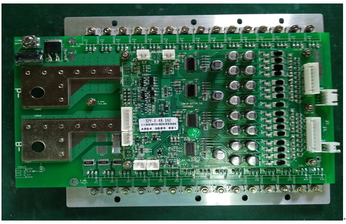
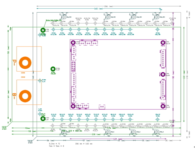
 3.Physical structure ( with 15 pairs of Mosfets) Copper screw bolts for the board are advised

4. Wiring Diagram and steps to install
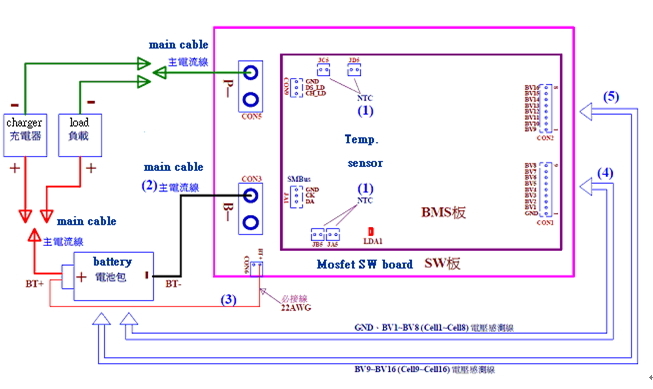
1. Steps to install battery pack with BMS. Please follow from (1) to (5)
(1) Plug temperature sensors, JA5, JB5, JC5, JD5 onto the BMS..
(2) "B─" at CON3 of the Mosfet switch board, connected to the "─” negative pole of battery pack.
(3) CON6 marked as "BT +" of the Mosfet switch board shall be connected to "+ (the positive pole)"
of the battery pack. This cable is used to conduct possible Back-EMF energy.
(4). On battery pack, its "GND, BV1 ~ BV8 (Cell1 ~ Cell8) voltage sense wires" shall be connected to
CON1 of the BMS board.
(5) On battery pack, its "BV9 ~ BV16 (Cell9 ~ Cell16) voltage sense wires" shall be connected to CON2 of the BMS board.
2. Steps to uninstall:
(1). Remove link on the "P─" at the CON5 of the Mosfet switch board, which connects to the "─ “
negative pole of the charger" or "load".
(2). Disconnect or unplug each of its connectors according to the reverse order of the installation, from
(5) – (4) – (3) - (2).