Smart battery management of SMBus via USB bridge tool to PC.
Wiring Diagram:
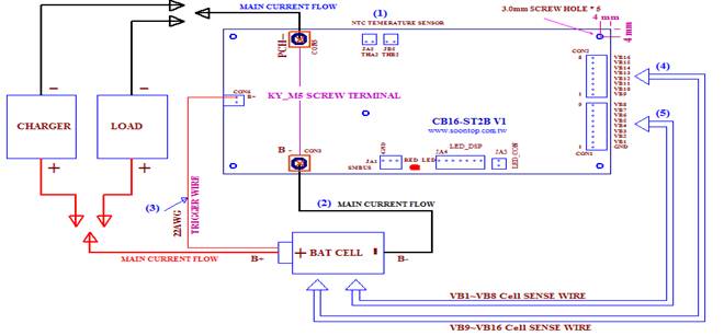
(1). Plug temperature sensors, JA5, JB5 onto the BMS.
(2). "B─" at CON3 of the Mosfet switch board, connected to the "─” negative pole of battery pack.
(3). CON6 marked as "BT +" of the Mosfet switch board shall be connected to "+ (the positive pole)" of the battery pack. This cable is used to conduct possible Back-EMF energy.
(4). On battery pack, its "GND, BV1 ~ BV8 (Cell1 ~ Cell8) voltage sense wires" shall be connected to CON1 of the BMS board.
(5). On battery pack, its "BV9 ~ BV16 (Cell9 ~ Cell16) voltage sense wires" shall be connected to CON2 of the BMS board.
(6). Charge the battery to try to wake up the BMS, if BMS has not been activated after installation.
After these, the red LED (LDA1) of BMS board will turn luminous for about 6 seconds, and then turns off. This red LED indicator will blink at an interval of every 8 seconds, indicating BMS normally operating.