
Feature:
1.USB tool kit ( SMBus protocol) connecting to PC to gather battery information.
2.Monitoring battery SoC and SoH, such as amperes, volts, capacity; temperature, protection status and cell balance, cycle life times, event records etc.
3.With circuitry of conducting back electromotive forces(BEMF)
4.Smart two-way cell balance design for both in charging and in quiescence.
5.LED display to show battery capacity, based on Coulomb Counter and, to show protection occurrences.
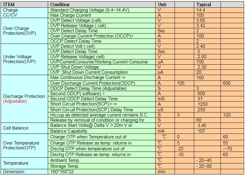
<1> Key Specifications:
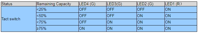
<2> LED Display (Option)
(1) Battery SOC LED Module
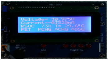
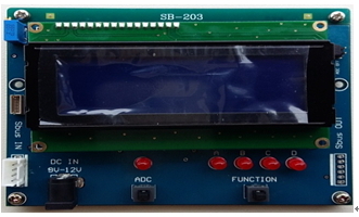
(2). Battery SOC LCD,with 4 display pages(Option),demands an external DC12V source
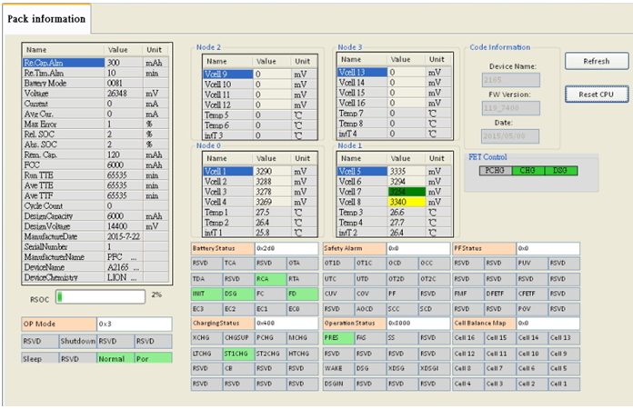
<3> Smart battery management of SMBus via USB bridge tool to PC. ( option, example on 8S)
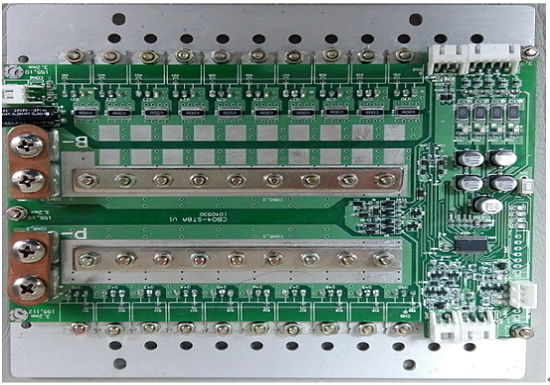
<4> Physical structure ( Dimension160*160*22)
<5> Wiring diagram for 4S BMS of the battery pack
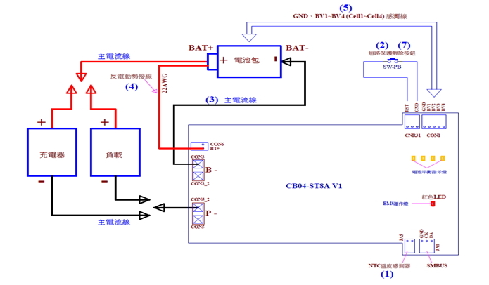
6. Steps to install battery pack with BMS.
1.Follow from (1) to (7)
(1) Plug temperature sensors, JA5, onto the BMS.
(2). Install the short-circuit(S.C.) removal switch CNR31.
(3) "B─" at CON3 of the BMS board, connected to the "─” negative pole of battery pack.
(4) CON6 marked as "BAT +" of the BMS board shall be connected to "+ (the
positive pole)" of the battery pack. This cable is used to conduct possible
Back-EMF energy.
(5) From battery pack, voltage sense wires of GND and BV1 ~ BV4 (Cell1 ~ Cell4) shall be connected to CON1 of the BMS board.
(6). Steps to wake up the BMS as shown in Item 3.
(7). If provided, the short-circuit (S.C.) protection switch shall be pressed to remove
S.C. status and have the BMS start up with operation for charging or discharging.
2. Steps to uninstall BMS:
(1). First of all, please remove the charger and loader on the battery pack,
(2). Disconnect or unplug each of its connectors according to the reverse order of the installation, from (5) – (4) – (3).
3. Steps to trigger up the BMS of the battery pack
(1). The positive pole of charger shall be linked to the”+” pole of battery pack.
(2). Make the negative pole of the charger touch onto the “P─" ( CON5) of the
BMS for1second.
(3). After these, the red LED (LDA1) of BMS board will turn luminous for about 6 seconds and then turns off,
(4). This red LED indicator will blink once for an interval of every 8 seconds,
indicating BMS normally operating.