Feature:
1.With a communication port for SMBus interface via USB tool kit to PC to gather battery information,
helpful for engineering or R&M services.
2.Monitor battery SoC and SoH, such as amperes, volts, capacity; and protection status and cell balance.
3.Smart cell balance design .
4.Electrical parameters are adjustable in default for customization, designed for 8S cells
Key specification: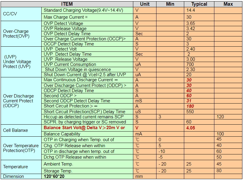
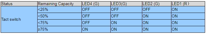
LED Display (Option)
(1)Battery SOC LED Module
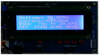
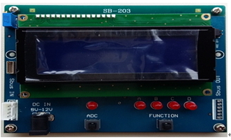
(2). Battery SOC LCD,with 4 display pages(Option),demands an external DC12V source.
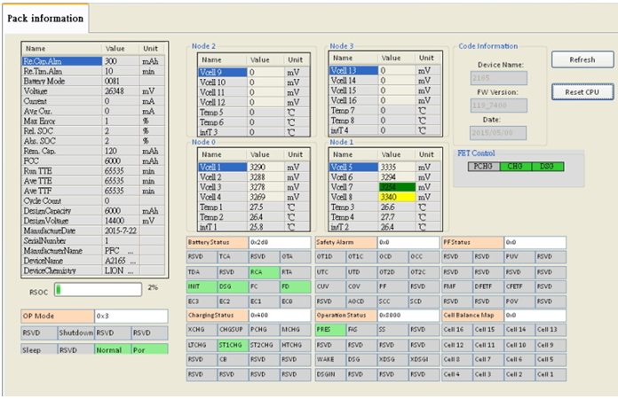
. Smart battery management of SMBus via USB bridge tool to PC. (Example over 8S)
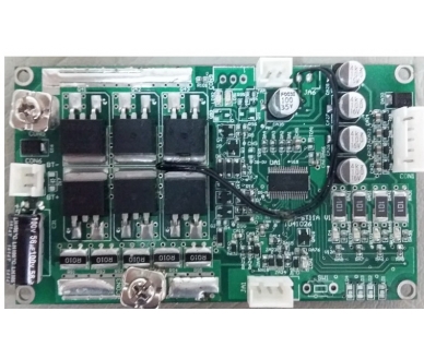
Physical dimension

< 5> Wiring Diagram:
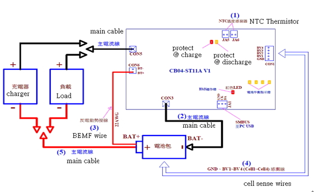
<6>. Steps to install battery pack with BMS:
1.Please follow from (1) to (5)
(1) Plug temperature sensors, JA5, JA6 onto the BMS.
(2) "B─" at CON3 of the board connects to the "─” negative pole of battery pack.
(3) CON6 marked as "BT +" shall be connected to "+ (the positive pole)" of the battery pack. This cable is
used to conduct possible Back-EMF energy.
(4) On battery pack, its "GND, BV1 ~ BV4 (Cell1 ~ Cell4) voltage sense wires" shall be connected to
CON1 of the BMS board.
(5) Charge the battery to wake up the BMS.
Please activate this BMS by doing as the following steps. If the red LED as being in normal operation does not blink for 6
seconds, and then turns off, which requires a trigger to activate it by charging signal.
2. Steps to uninstall:
(1). Remove link on the "P─" at the CON5 of the Mosfet switch board, which connects to the "─ “
negative pole of the charger" or "load".
(2). Disconnect or unplug each of its connectors according to the reverse order of the installation, from
(4) – (3) - (2).